After the concrete foundation has a compressive strength of more than 75%, the ball mill can be installed on it. Before the installation, the quality of the foundation should be inspected, and the concrete is required to have no defects affecting the strength. The number and position of the reserved holes meet the requirements, and there is no debris and water in the hole, and no oil. When using the "grounding method" for installation work, the "central target" should be embedded on the surface. Draw all the centerlines on the basis of the installation and make a striking punch mark on the “Center Mark†as the centerline reference for installation. Before the hoisting, the ball mill should be fully examined and accepted, and the problems should be dealt with in a timely manner. 1. For the specific requirements of the main bearing part, refer to the assembly drawing of the main bearing parts. 2. Refer to the assembly drawing of the swivel part for the cylinder part. 3. Refer to the assembly drawing of the transmission part for the transmission part. 4. Refer to the assembly drawing for the overall relative position. General requirements for installation of energy-saving mills: 1, the installation of the host: The axis of the main machine of the mill should be horizontal, measured at the top of the hollow shaft at both ends, and the height should be consistent. When there is an error, the feeding end is allowed to be 1 mm higher than the discharge end. Look at the gland of the hollow shaft at both ends, hollow The gap between the shaft and the bearing gland should be basically the same, and the gap between the inner and outer gland should be basically the same. 2. Installation of the transmission part: After the main unit has been adjusted to the level, the transmission part can be installed. First check the quality of the assembly of the transmission part, mainly to check the concentricity of the pinion shaft and the low speed shaft of the reducer, check the concentricity of the high speed shaft and the motor shaft of the reducer, and make necessary adjustments and tightening. Install and adjust the drive section based on the mainframe gear. Make the pinion gear width wider than the tooth surface of the large gear. The tooth surface of the pinion gear is parallel to the tooth surface of the large gear, and the tooth side gap is left at a minimum of 0.25 mm (about one layer of hard-packed cigarette wrapper). From the contact marks of the large and small gears, the contact marks should account for more than 60% of the total length, and the height of the contact marks accounts for about 40% of the full height. If the contact trace is biased towards one end of the flank width, it indicates that the flank is not parallel. If the transmission gear is crushed in a week, the gear clearance is too small, so the pinion should leave the big gear a little. 3, fault judgment: The bearing is hot and check for oil shortage. The main bearing and pinion shaft bearings are lubricated with grease, and the reducer is lubricated with oil. If there is no shortage of oil, check the concentricity of each part and check the main unit and the transmission part separately. The large bearing seat is not concentric with the hollow shaft, causing the hollow shaft to frictionally generate heat with the bearing gland. The pinion shaft of the drive is not concentric with the bearing housing, causing friction between the drive shaft and the bearing gland. If the reducer and the pinion shaft are not concentric, and the reducer and the motor are not concentric, the bearing will be overloaded and heated. When the hollow shaft is not completely different from the large bearing seat, it may cause difficulty in starting, power consumption during operation, and heat generation of the motor. Therefore, it is very important to ensure the concentricity of each part during installation. 4, the installation of the mill liner 1. Remove dust from the cylinder before installing the liner. 2. When installing the lining, a layer of 1:2 cement mortar should be applied between the inner wall of the cylinder and the lining, and the lining bolts should be tightened by dampness. The gap between the linings is also smoothed with sand and pulp. 3. The bolts of the fixed lining should be carefully padded to prevent leakage of the slurry. 4. Before installing the lining, the lining should be inspected and trimmed. The back and sides should be smooth and flat. The bolt holes should be thoroughly cleaned and the casting burrs should be removed so that the bolts can penetrate smoothly. The north and the periphery should be trimmed with a grinding wheel as appropriate to meet the installation requirements. 5, the directional liner should pay attention to the direction can not be reversed. The long mill generally divides the grinding cylinder into two compartments by the compartment plate. The feed end is the first bin and the first bin is the step liner. When installing, the thin end of the step liner should be in the same direction as the arrow in the direction of rotation of the mill. The raft hole of the partition plate is tapered, and the big end of the cone should be aligned with the discharge direction of the mill. 6. When installing the compartment board, all the bolts should be worn, and then the bolts should be tightened step by step. At the same time, it should be noted that the bolts on the cylinder body should be tightly connected to the center disc of the cylinder. After the bolts are all tightened, the nuts of the bolts on the center disc in the cylinder body are "spot welded" by electric welding to prevent loosening. 7. The cylinder liner shall not form an annular gap. 8. After the cement mortar has been solidified to the strength requirement, it can be put into trial operation. Loose bolts should be tightened in time during operation. Derrick DP600 PMD Shaker Screen
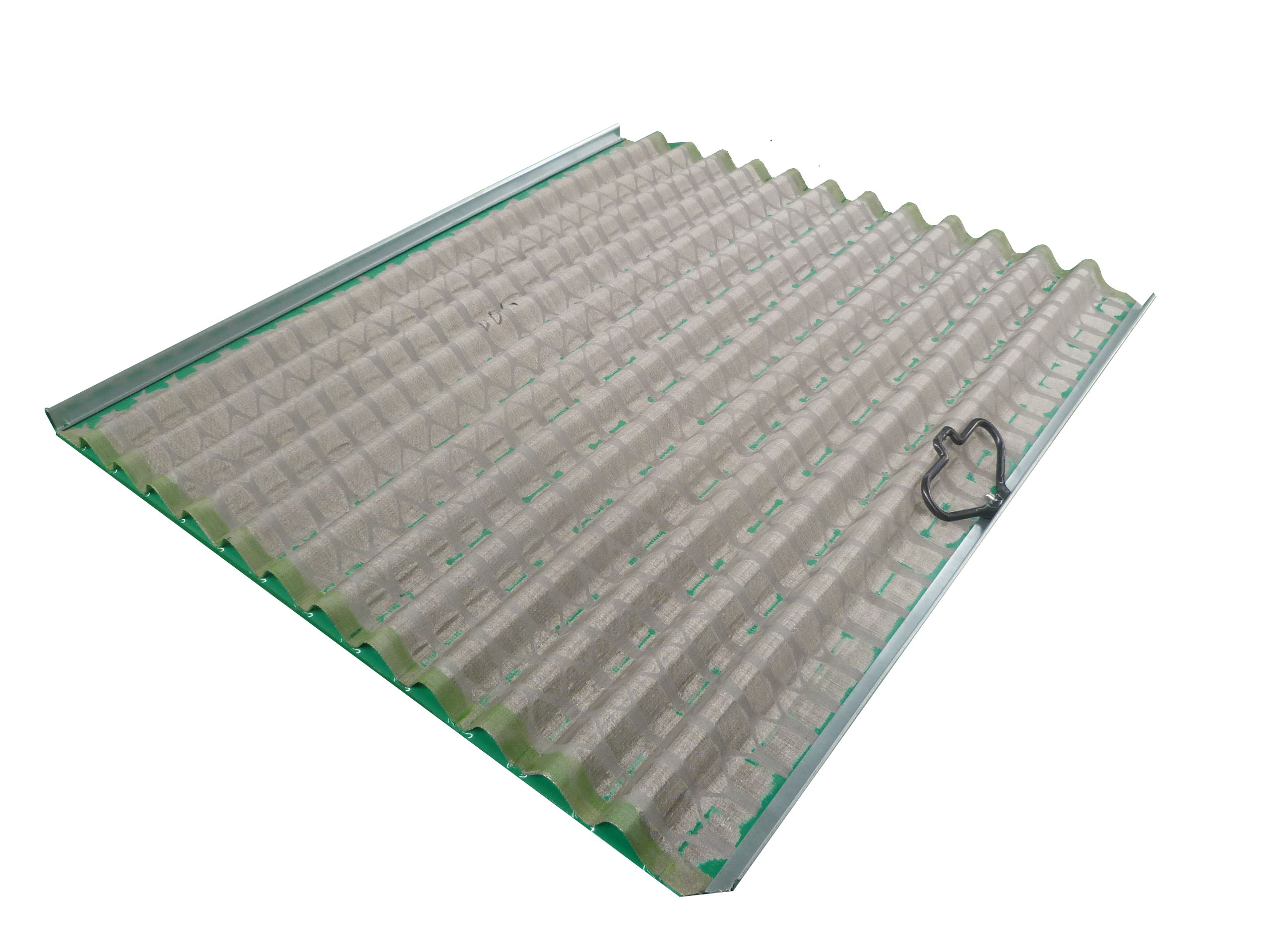
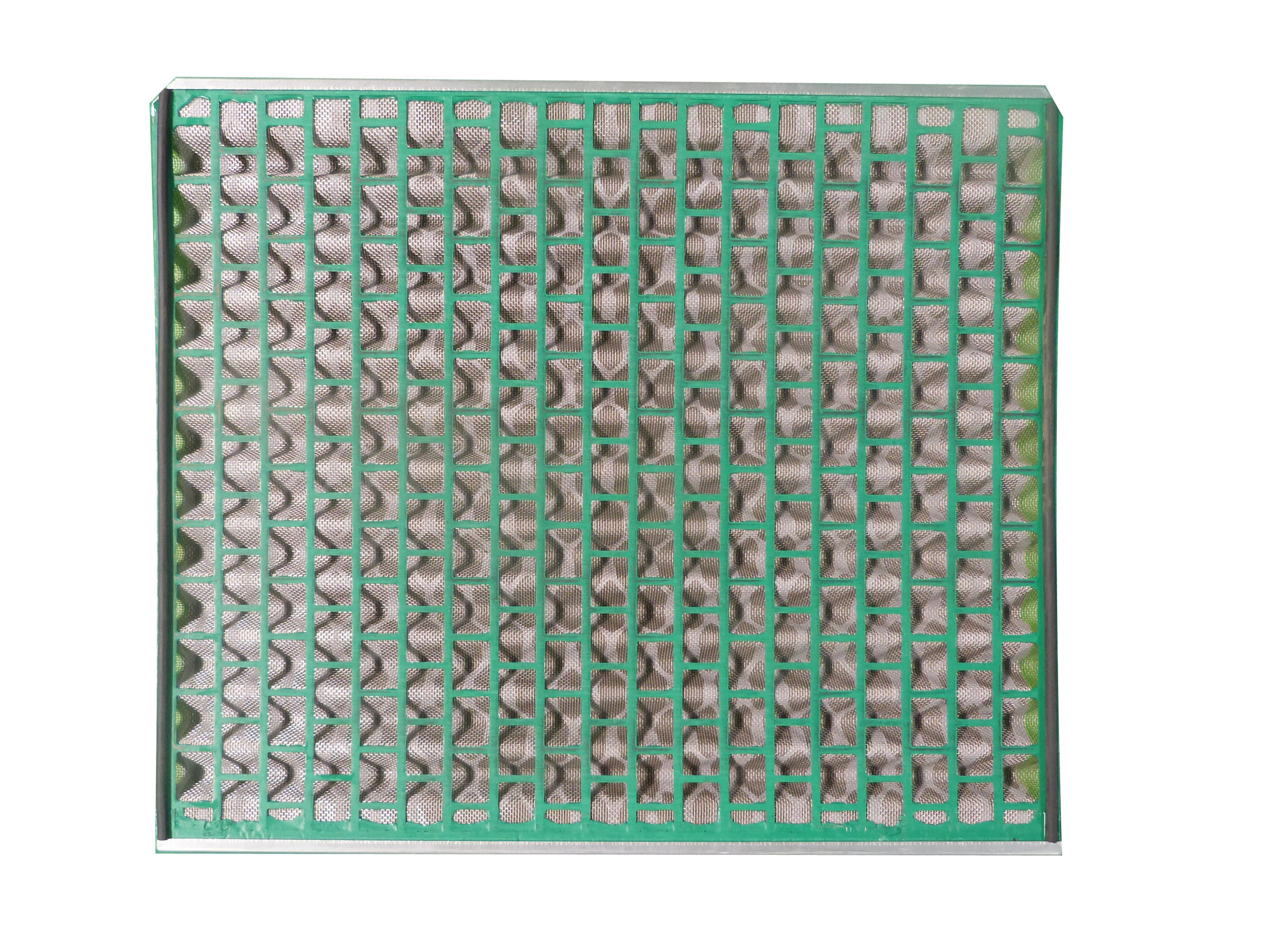
Derrick DP 600 PMD Shaker Screen
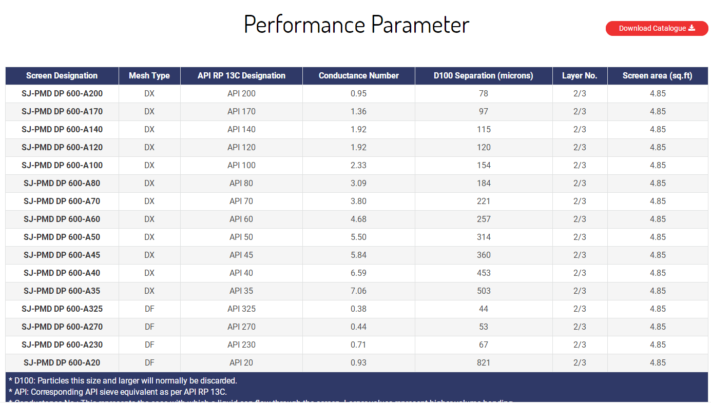
SJ-PMD DP 600 shaker screen with dimension of 626 × 710 mm which is smaller than other screen panels, it is the replacement screen for Derrick Dual pool 600 series shale shakers. There are 6 or 8 panels needed for each DP 600 shaker. Innovative actuated screen compression system drives the center of the screen panel downward and firmly sealing the screen panel to the screen frame. The mud recovery is greatly improved.
Technical Parameter
Adaptable Shale Shaker Model
SJ-Derrick DP600 PMD shaker screen are used to as the substitute screen for:
Remarks:
Derrick, DP 600, PMD, DX, DF, HP are marks of Derrick Corporation.
ShengJia only produces the replacement screens but not original from Derrick
Derrick Dp600 Pmd Shaker Screen,Derrick Flc600 Shaker Screen,Derrick Flc600 Shale Shaker Screen,Derrick Flc600 Pyramid Shaker Screen Anping Shengjia Hardware Mesh Co.,ltd , https://www.oilshakerscreen.com
The ball mill should be mounted on a solid concrete foundation. For the basic design and construction of the ball mill, please refer to the ball mill assembly drawing and foundation drawing. In order to ensure that the positional accuracy of the various parts of the ball mill does not change greatly during use, the foundation of the ball mill should adopt a monolithic structure.
Replacement PMD Screens Derrick DP 600 Series Shakers
Competitive Advantage


